Research · Representing physical intent

Design-intent compilation

Designs that state what an object should do, compiled into the materials and process settings each printer needs.

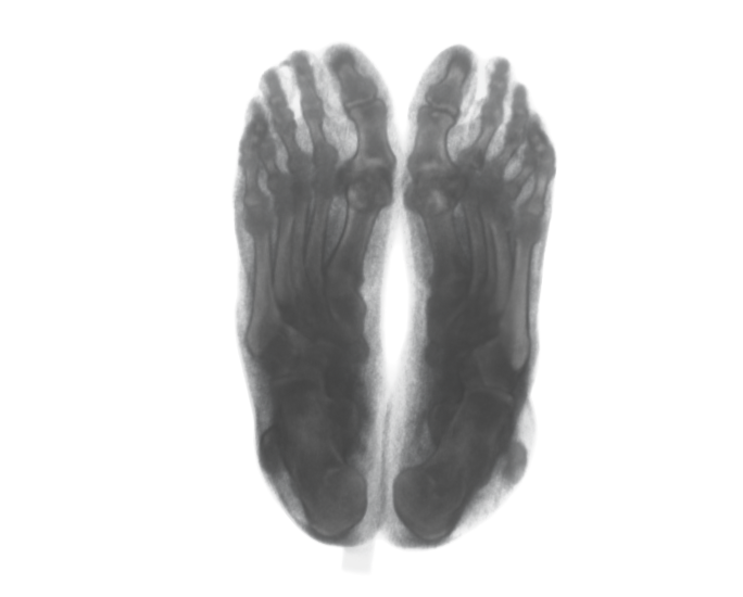
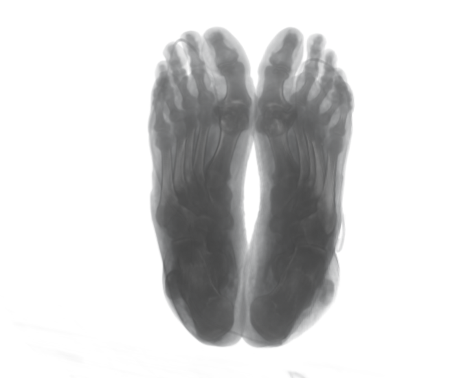
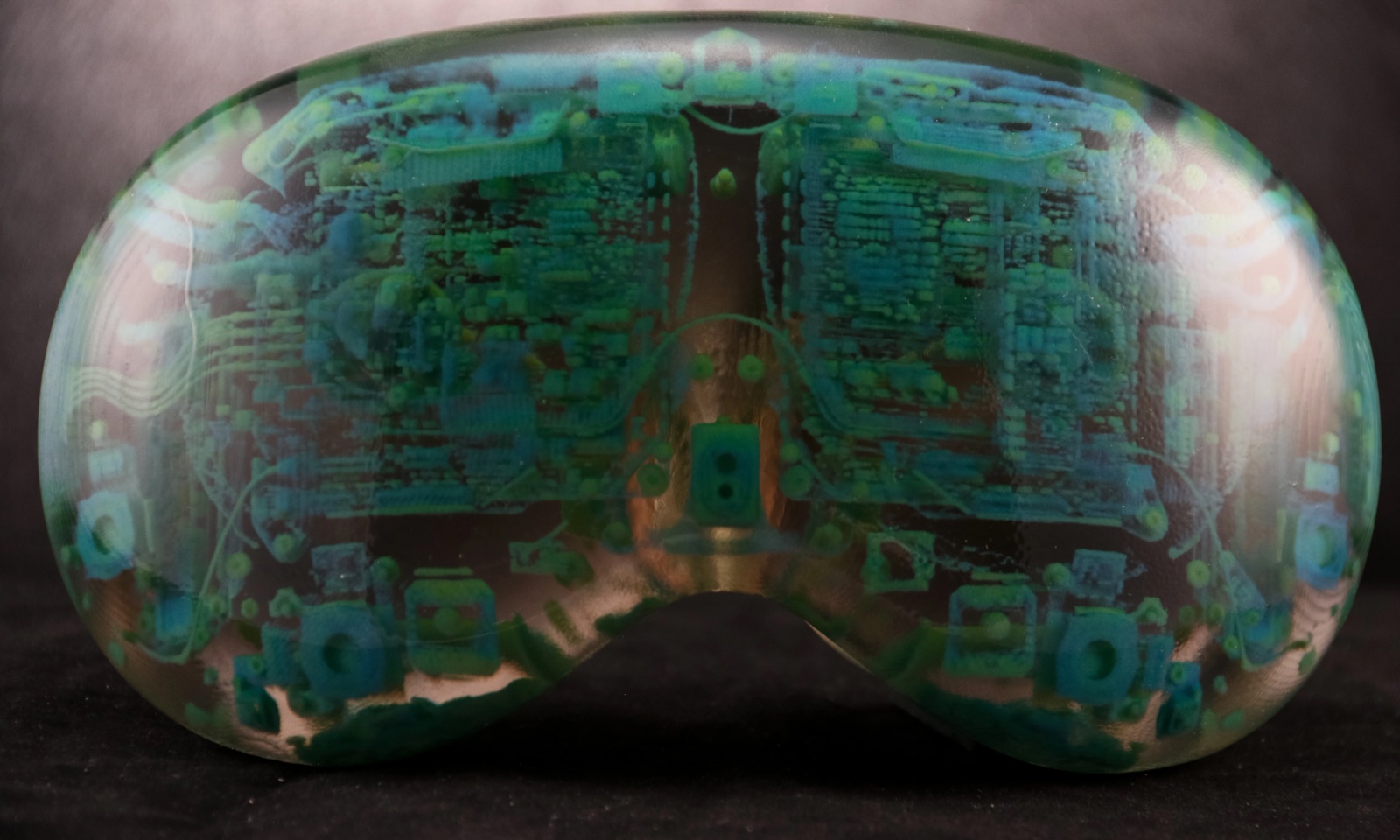
What I mean by intent. Design intent is what an object should do or be: the properties you would ask for, such as a hardness, a stiffness, a color, or how the part should appear in a CT scan. It is not the machine-specific settings used to make it, such as material fractions, nozzle temperatures, or toolpaths. Design-intent compilation keeps a design in terms of the first and derives the second automatically for each printer.

Designers should not have to manage every step from intent to print. Design-intent compilation stages them, so desired properties become spatial fields and material and process models turn those fields into a printable file.

The problem. Most 3D printing workflows ask designers to specify machine settings, such as material fractions, nozzle temperatures, or slicer regions, instead of the properties they actually want. The design is then tied to one printer, and its purpose is lost.

The idea. Programming languages solved a similar problem: programmers write what a program should do, and a compiler produces the machine code. Design-intent compilation applies that idea to fabrication. A design describes geometry and the properties each region should have. Process and material models, calibrated once for each printer, translate those properties into machine settings.

Side-by-side comparison of programming (code, compile, execute) and the proposed fabrication workflow (design, compile, print), where each describes intent and a compiler translates it into machine instructions
Programmers describe what a program should do, not how the computer runs it. Here, designers describe what an object should do, not how the printer builds it.

Key result: one design, many printers

Because a design states intent rather than machine settings, the same design can be compiled for printers that work in completely different ways. A single hardness design was printed on an inkjet printer, which mixes soft and rigid resins, and on a filament printer, which controls how much a foaming TPU expands by changing nozzle temperature. Both matched the requested hardness.

Photos of an inkjet-printed bar and a foaming-TPU bar above a plot where both measured hardness profiles closely follow the designed 65A to 85A gradient
One hardness design, two processes. A bar designed to grade from 65A to 85A, shown as photos of the inkjet-printed and FFF-printed (foaming TPU) bars. Measured hardness follows the design in both (mean absolute error 0.3A and 0.5A).
Insole hardness design feeding computed temperature, flow-rate, and volume-fraction fields, with the resulting blue filament print and brown inkjet print
At application scale. An insole with a soft heel and firmer arch, compiled from one hardness field into nozzle temperature and flow for foaming TPU, and into soft and rigid material fractions for inkjet. The bottom row shows the FFF-printed and inkjet-printed insoles.
A mountain-scene reference image above four printed versions, two by inkjet and two by filament printing
Beyond mechanics. One color image compiled for material jetting (dithered and stochastic) and for filament printing (Prusa ColorMix and Orca FullSpectrum). Each panel is a photograph of an inkjet- or FFF-printed part. Material jetting reproduced color most accurately, and the comparison quantifies what each process trades off.

This work is with Devon Beck (Draper) and Robert MacCurdy, and the framework is released as part of OpenVCAD.
Publications

  1. Design-Intent Compilation for Heterogeneous Fabrication
    Design-Intent Compilation for Heterogeneous Fabrication
    Charles Wade, Devon Beck, and Robert MacCurdy
    2026
    In submission · arXiv preprint