Large 2 “Stacking Up”
3D Parametric Design and Slicing of Laser Cut Objects
Task 1
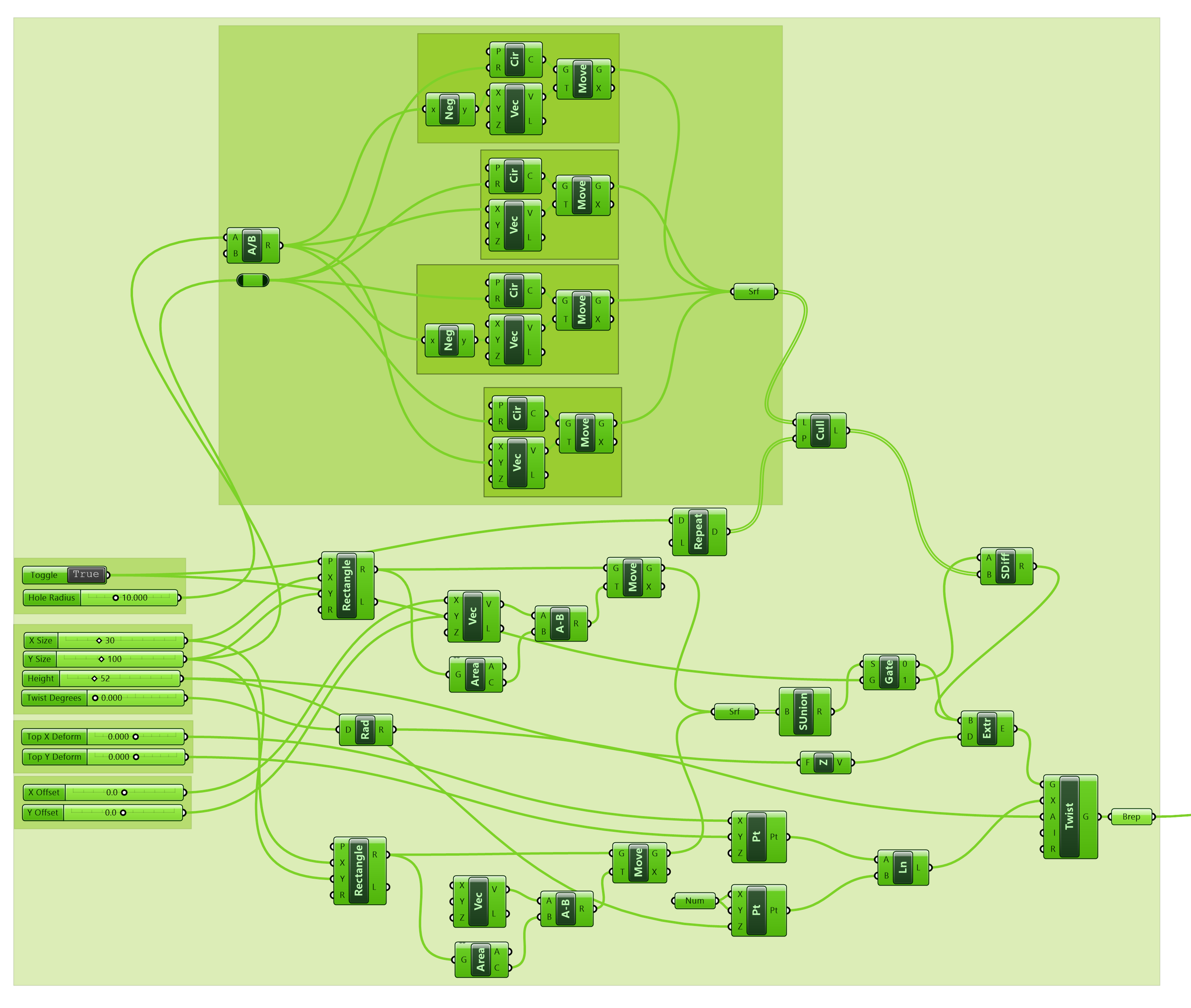
For this section, I created a cross-shaped object that can be controlled with 10 parameters. The image below shows how this object is created step by step. The table below explains design each parameter.

| Name | Description |
|---|---|
| Hole toggle | Enables/ disables the holes |
| Hole radius | How big to make the holes |
| X-size | Size of cross in x-dim (mm) |
| Y-size | Size of cross in y-dim (mm) |
| Height | Height of object |
| Twist Degrees | Amount to twist extruded object (deg) |
| Top X Deform | How much to rotate the top plane of the object by in X |
| Top Y Deform | See above |
| X-offset | Can be used to make cross asymmetric |
| Y-offset | See above |
Grasshopper Script
Design Gallery


Task 2
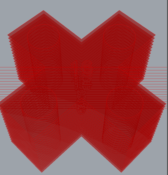
The initial step in slicing an object involves determining the necessary number of slices based on the object’s height. To accomplish this, I employ a bounding box to determine the z-height. Subsequently, I divide this value by the user-defined material height using integer division. Utilizing the derived layer count, I generate a sequence of values. Following this, I leverage the layer height to establish a series of z-offset planes. Each plane is then intersected with the design’s boundary representation (b-rep), yielding a set of curves for each layer. At this point, it is important to exercise carefully manage multiple curves, such as those representing holes. The image below provides a visual representation of what the slicing result appears like at this stage.

Following the slicing, the subsequent step involves eliminating any curves too small for laser cutting. For this purpose, I applied an area filter. The next challenge is to build the index text for each layer’s identification. This task was complex, as determining suitable locations for text placement heavily depends on the geometry of a layer. I decided that positioning the text at the center of each layer would be the most effective strategy. Likewise, the “text on surface” component required a directional line for the text orientation. To achieve both goals, I used the 2D bounding box of each sliced layer. By selecting two opposite corners of the bounding box, I was able to create a line that serves both to orient and center the text. I experimented with generating the text at the origin and then moving it to the layer, but this method was ineffective because the move command moved each letter independently around its center. The image below illustrates the line on each layer, with the index text generated through a series component based on the number of layers remaining after area culling.
The final step is to move each layer (with text) to the floor. During this step each layer is fist translated down to the floor. Next, a series is used to spread each slice out using a user defined distance.
Note: a place this could be improved would be to use the bounding box to pack the slices

Grasshopper Script

Task 3
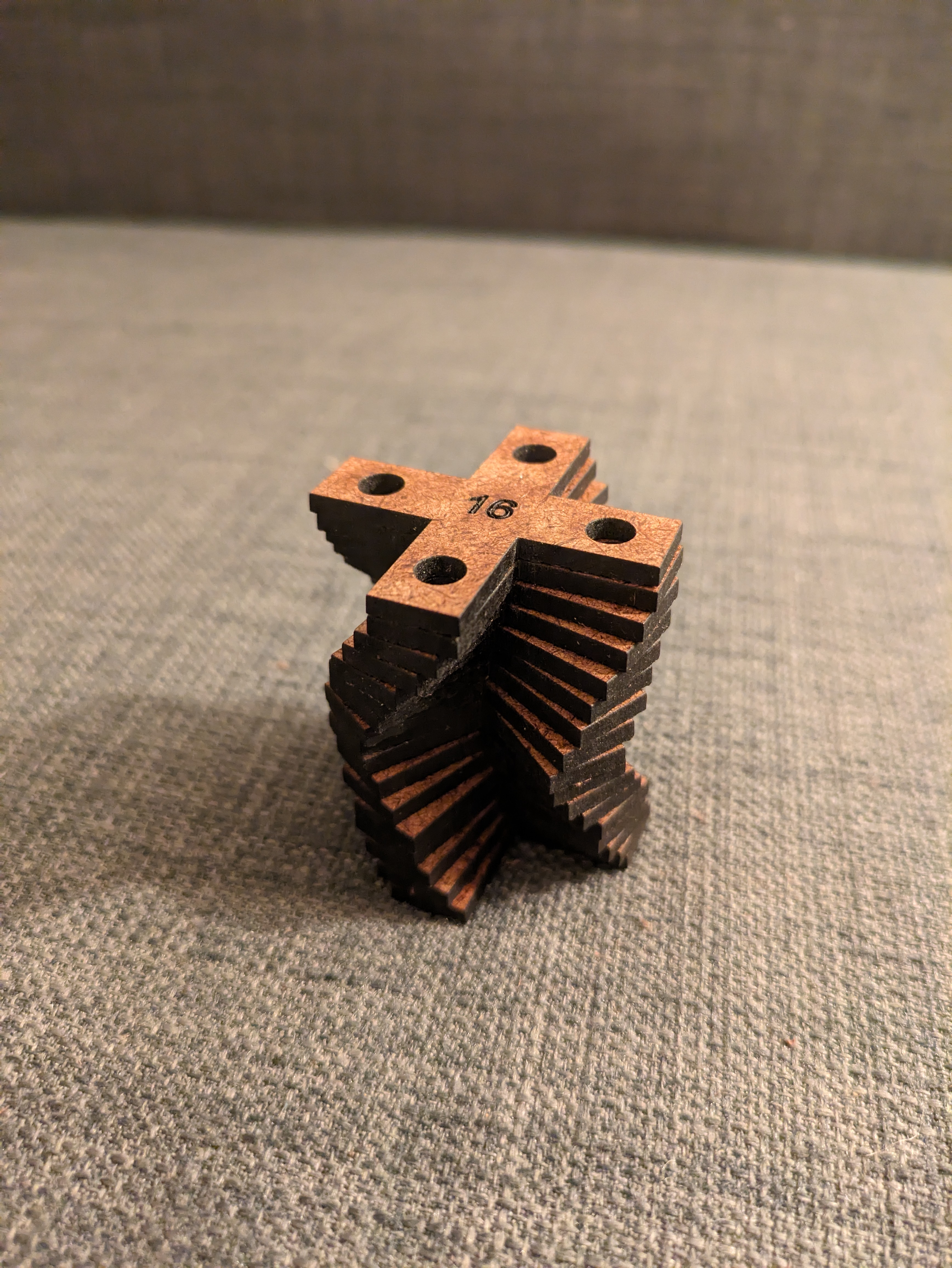
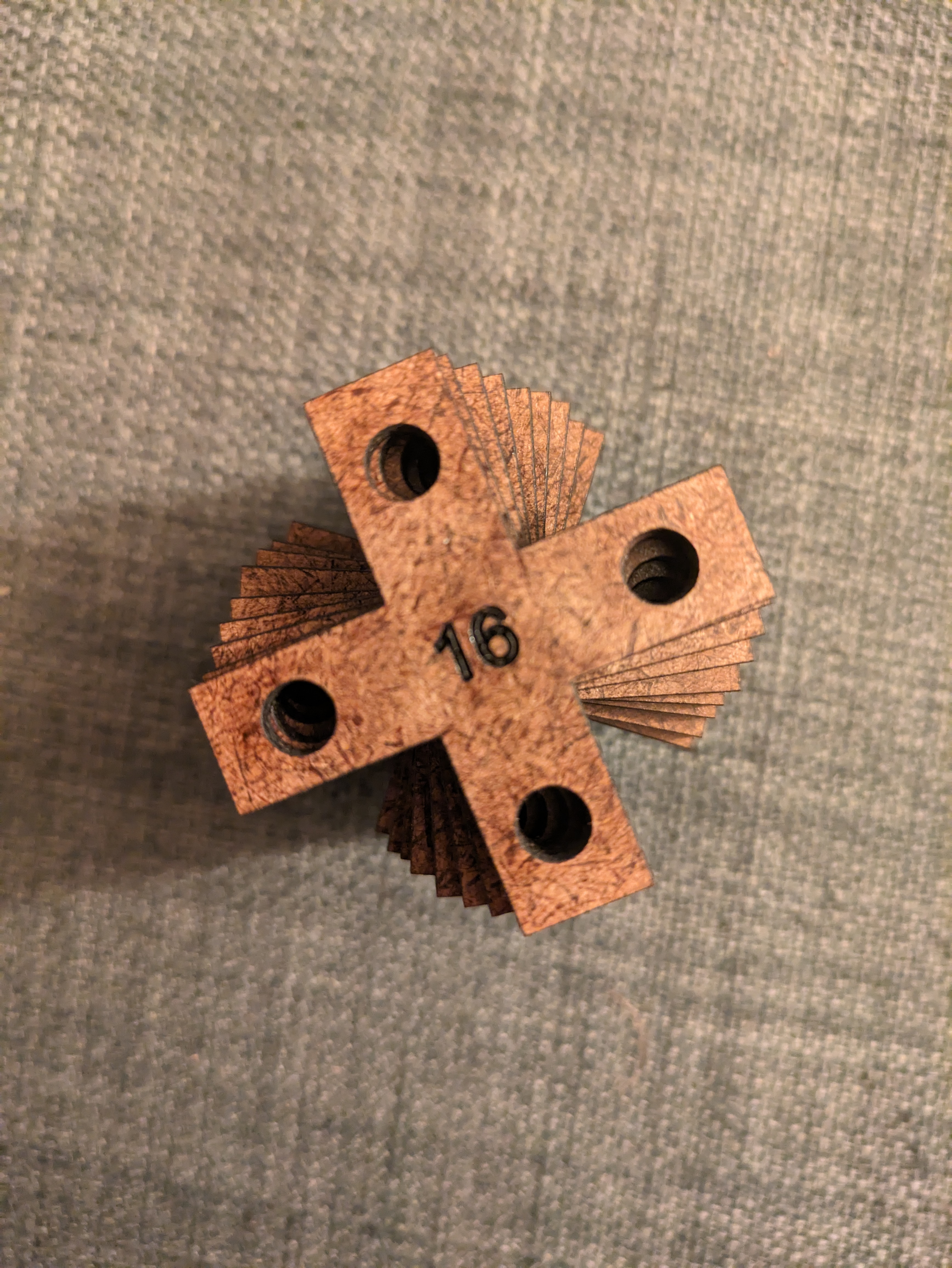
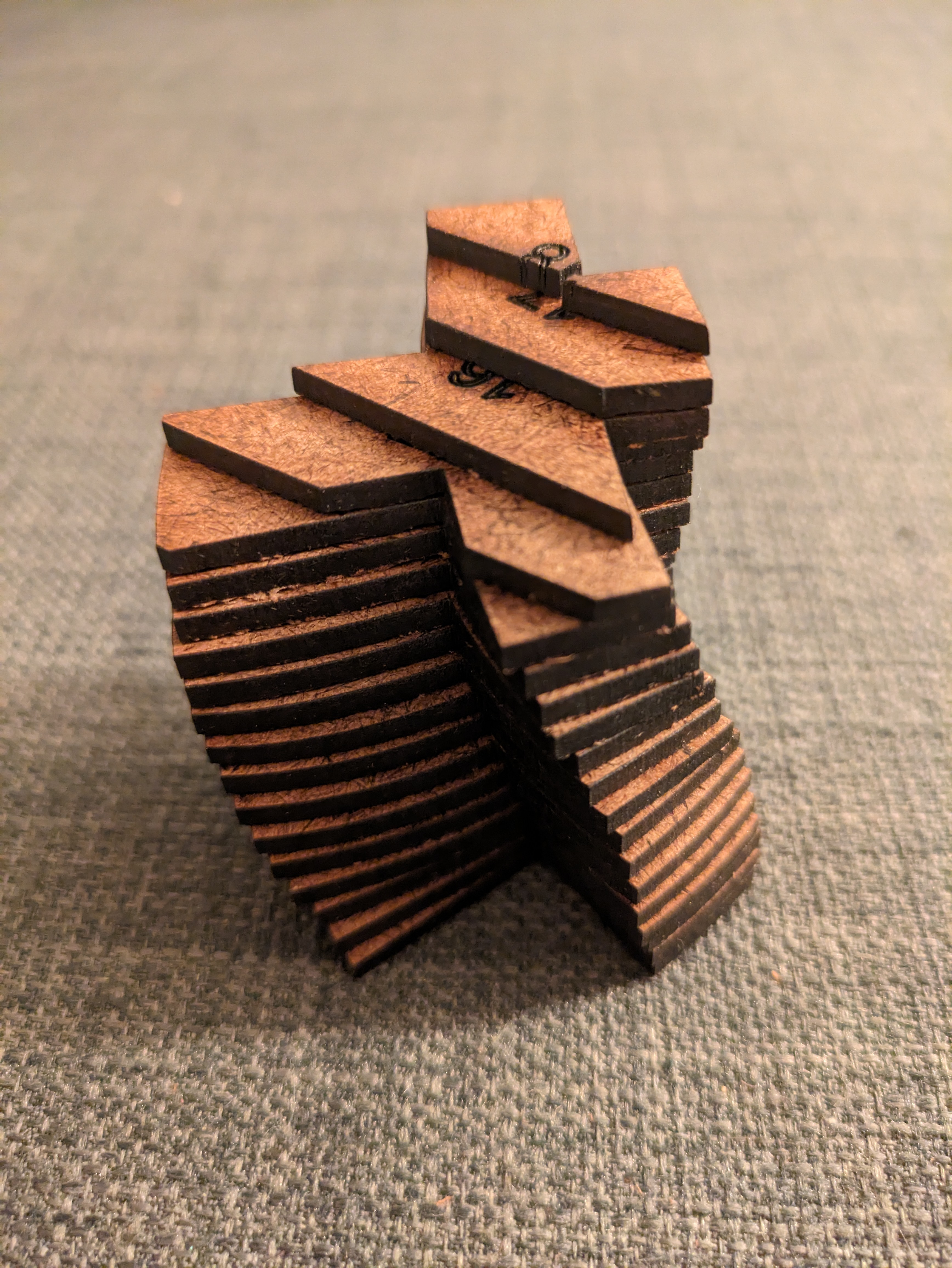
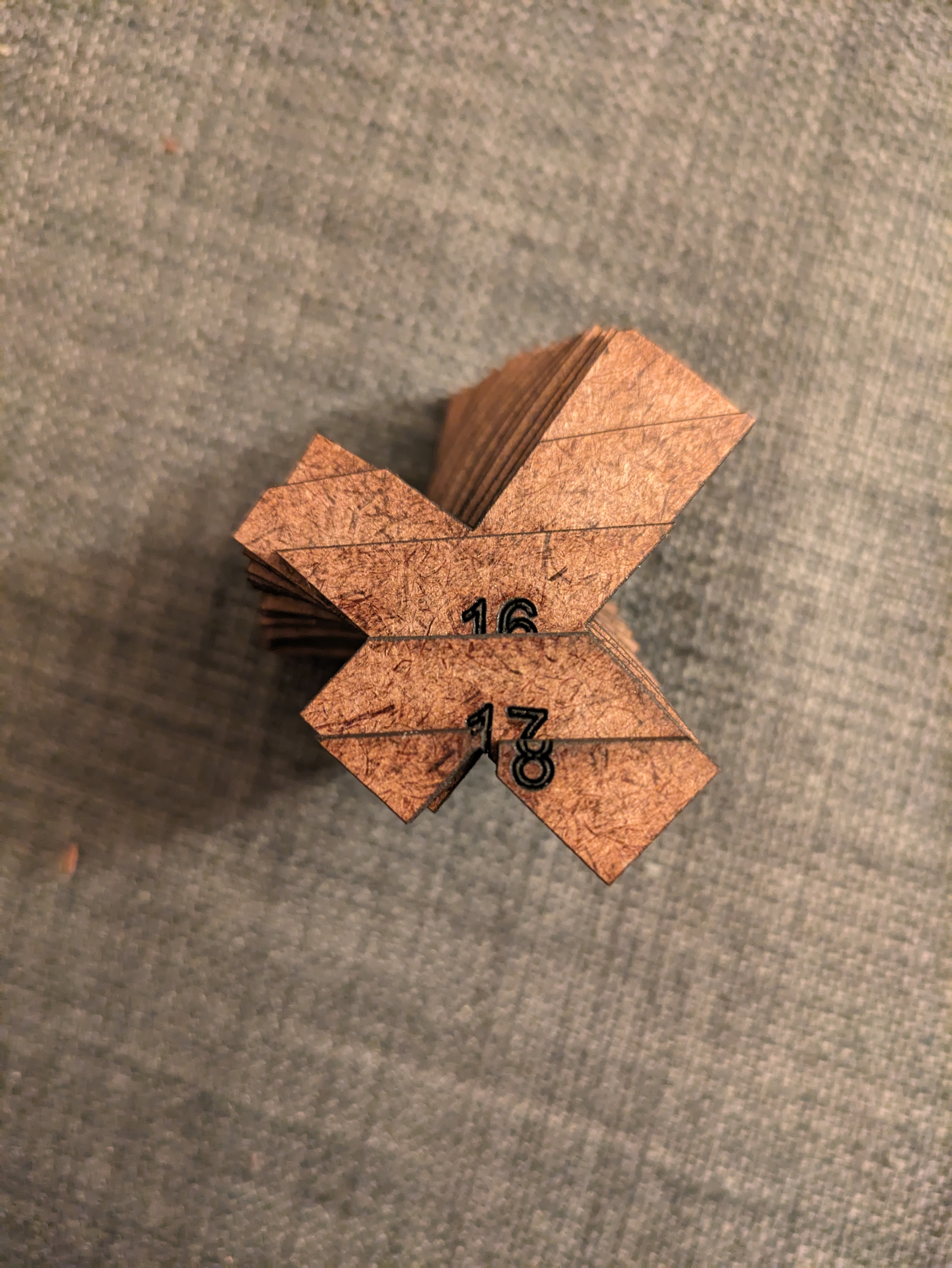
Fabricated Objects
All objects were created using 1/8 in MDF.
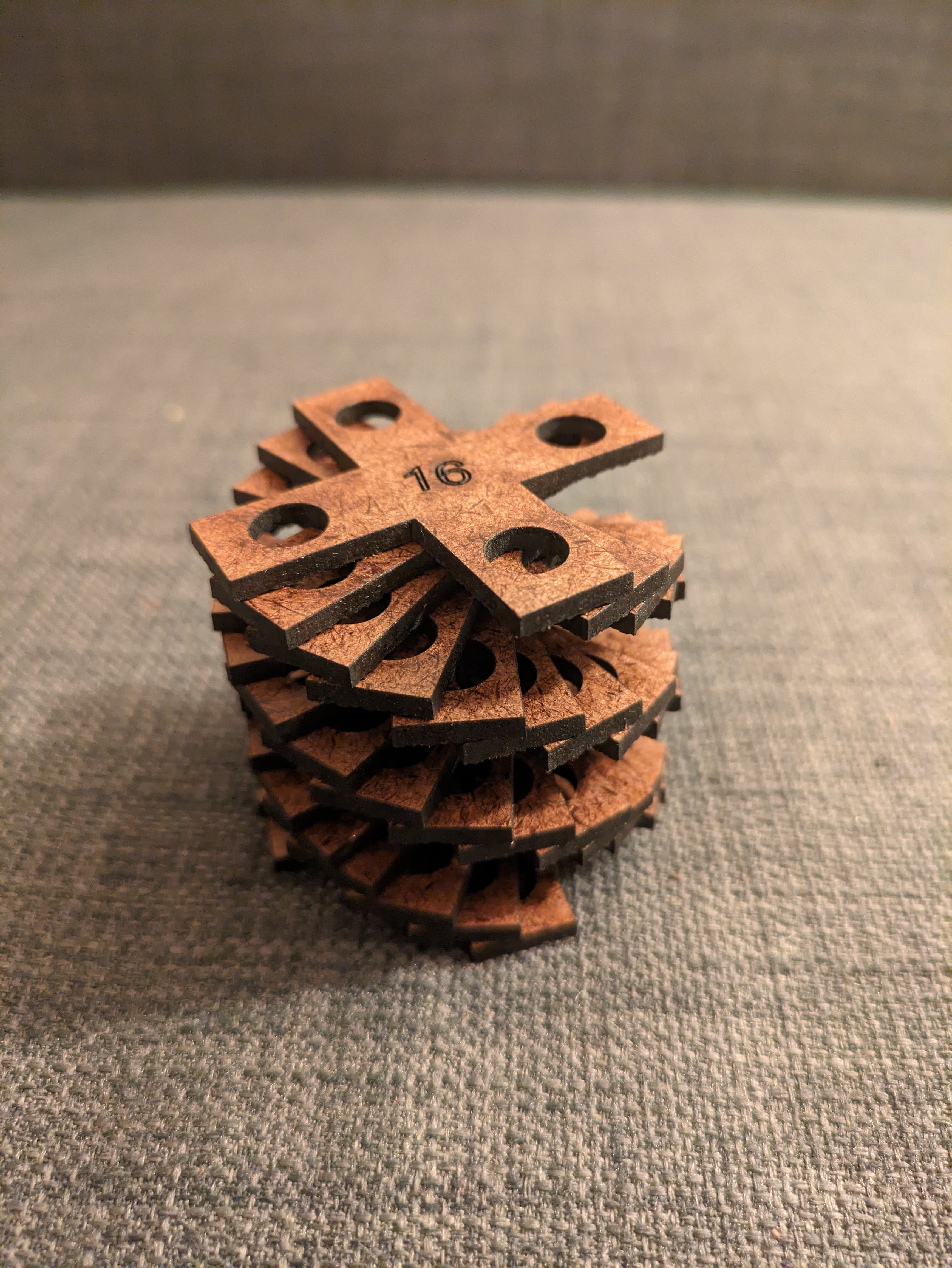
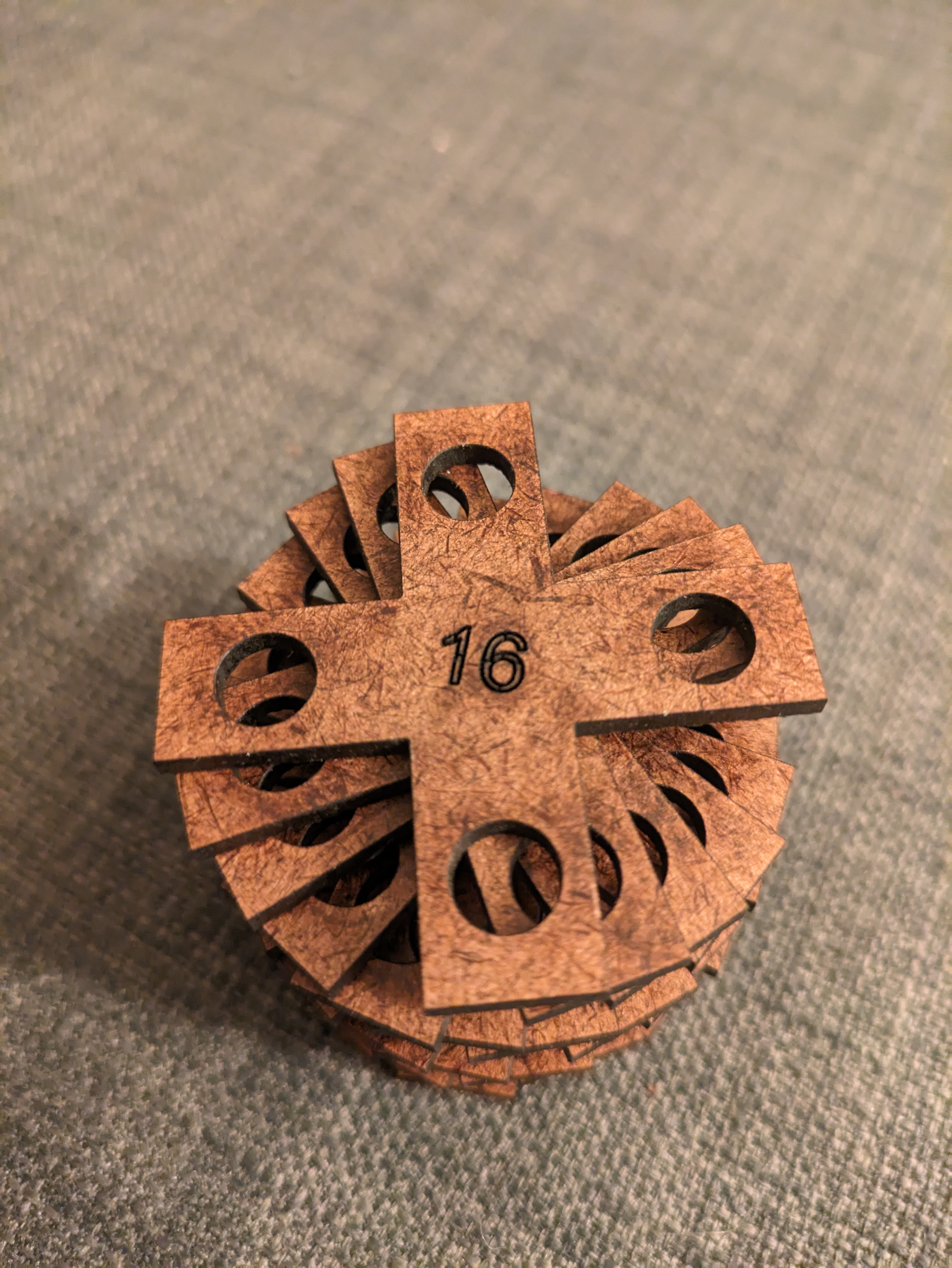
Fabrication Process
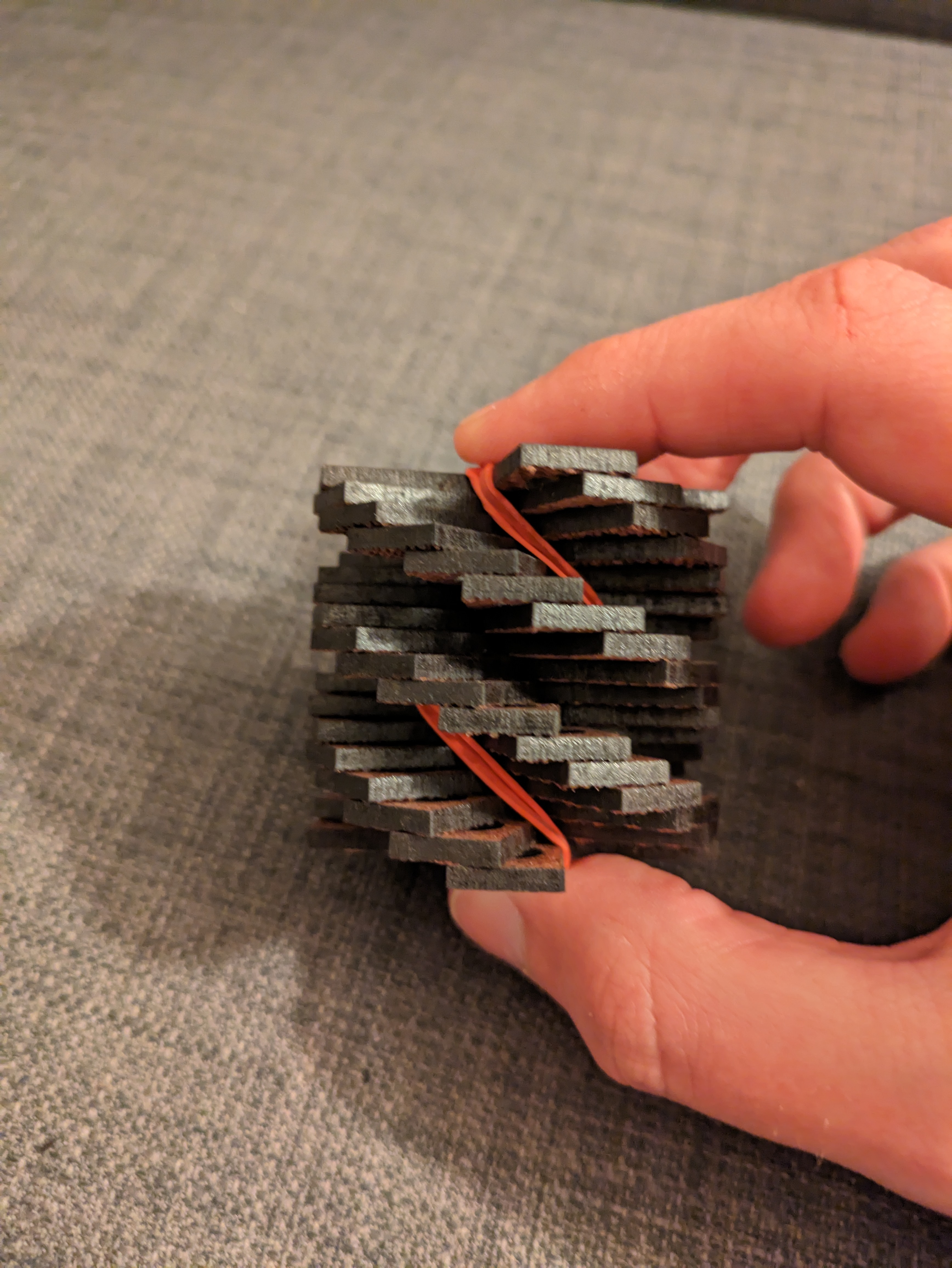
All objects were glued using wood glue. One trick I found for the twisted objects was to apply the wood glue between the layers quickly and stack them in a straight line. I then wrapped the object in a rubber band and twisted them to the correct angle. This automatically aligned each slice to the correct angle and applied a clamping force downward. See the picture below.
Extra Credit
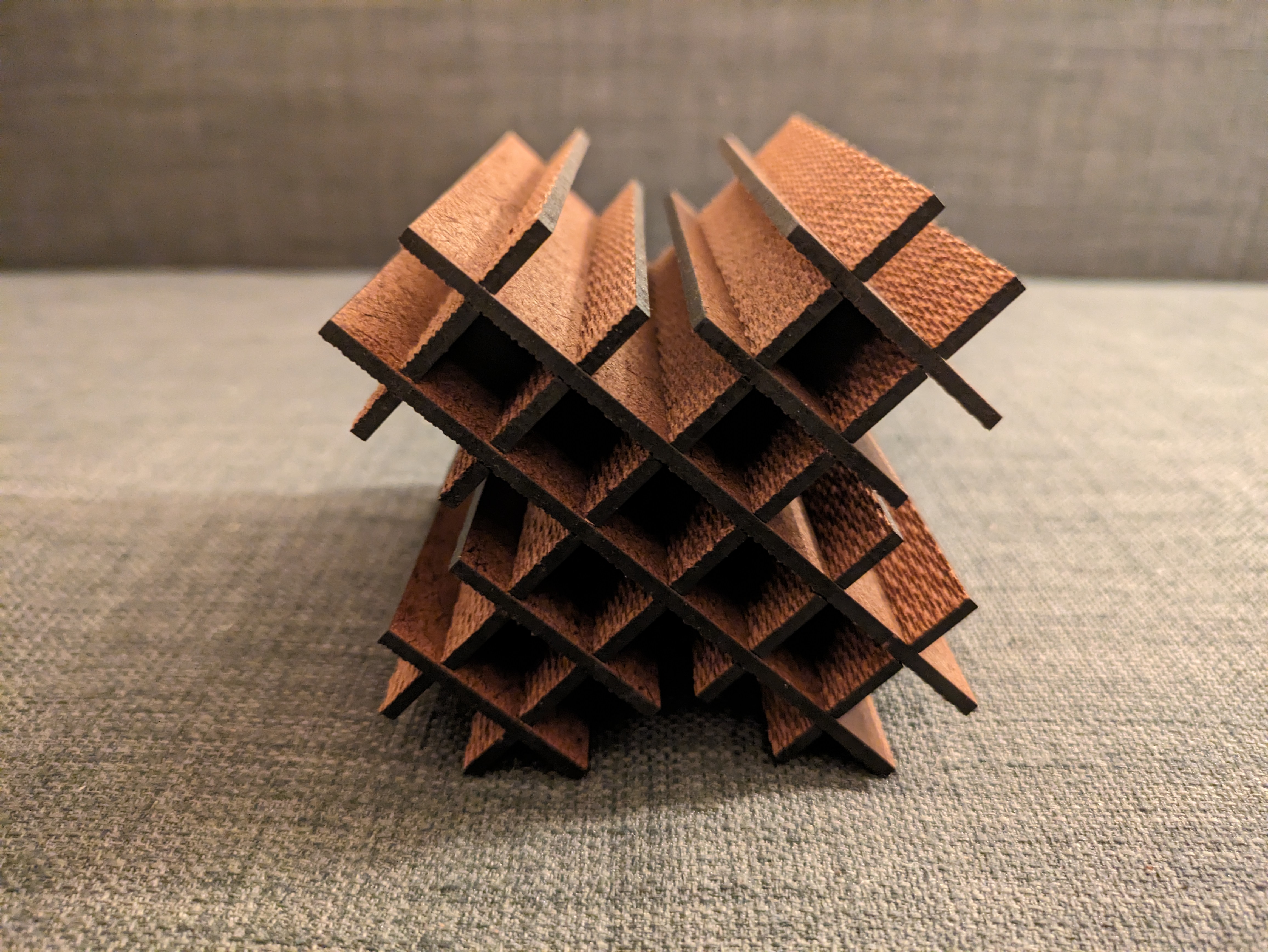
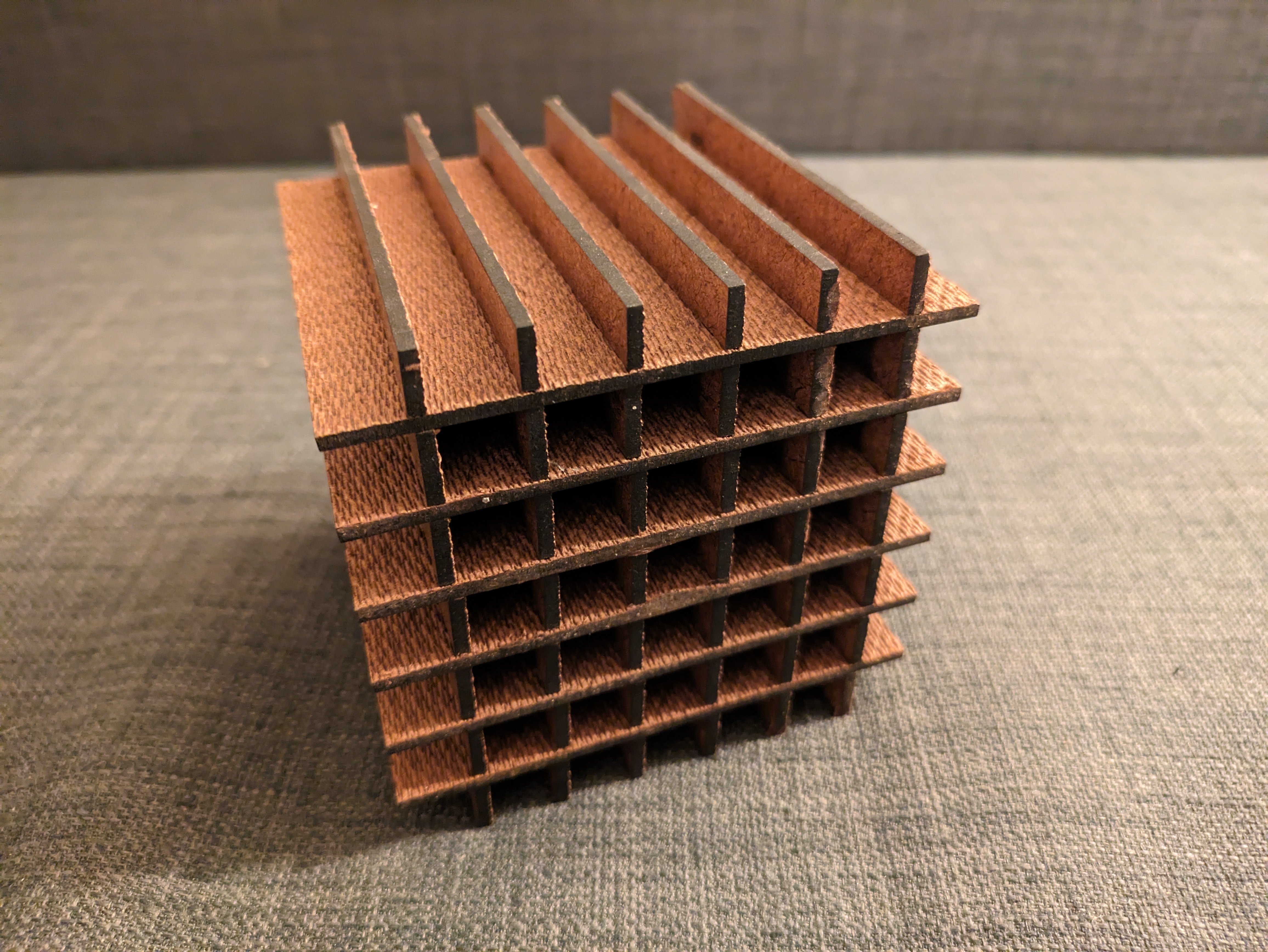
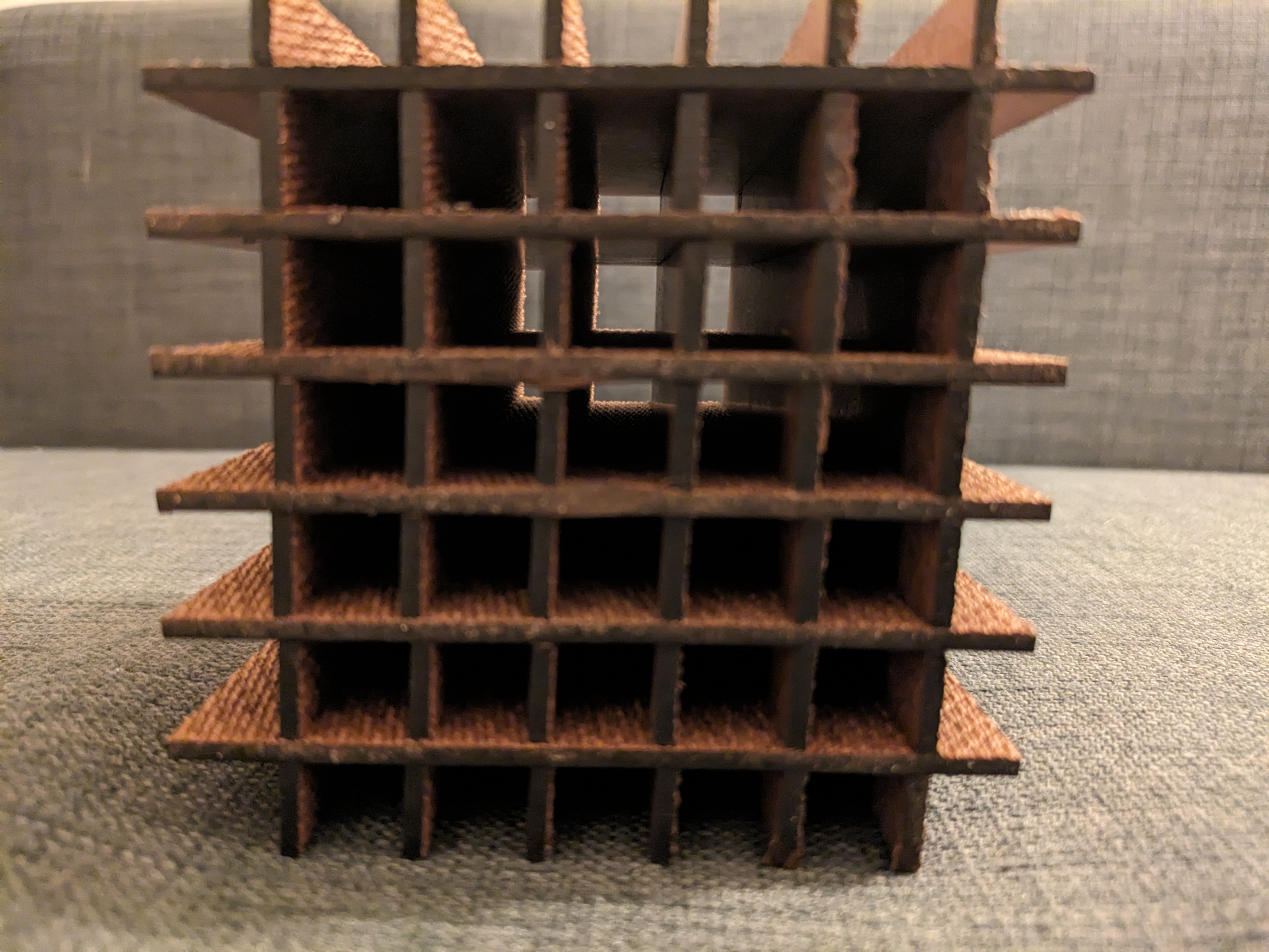
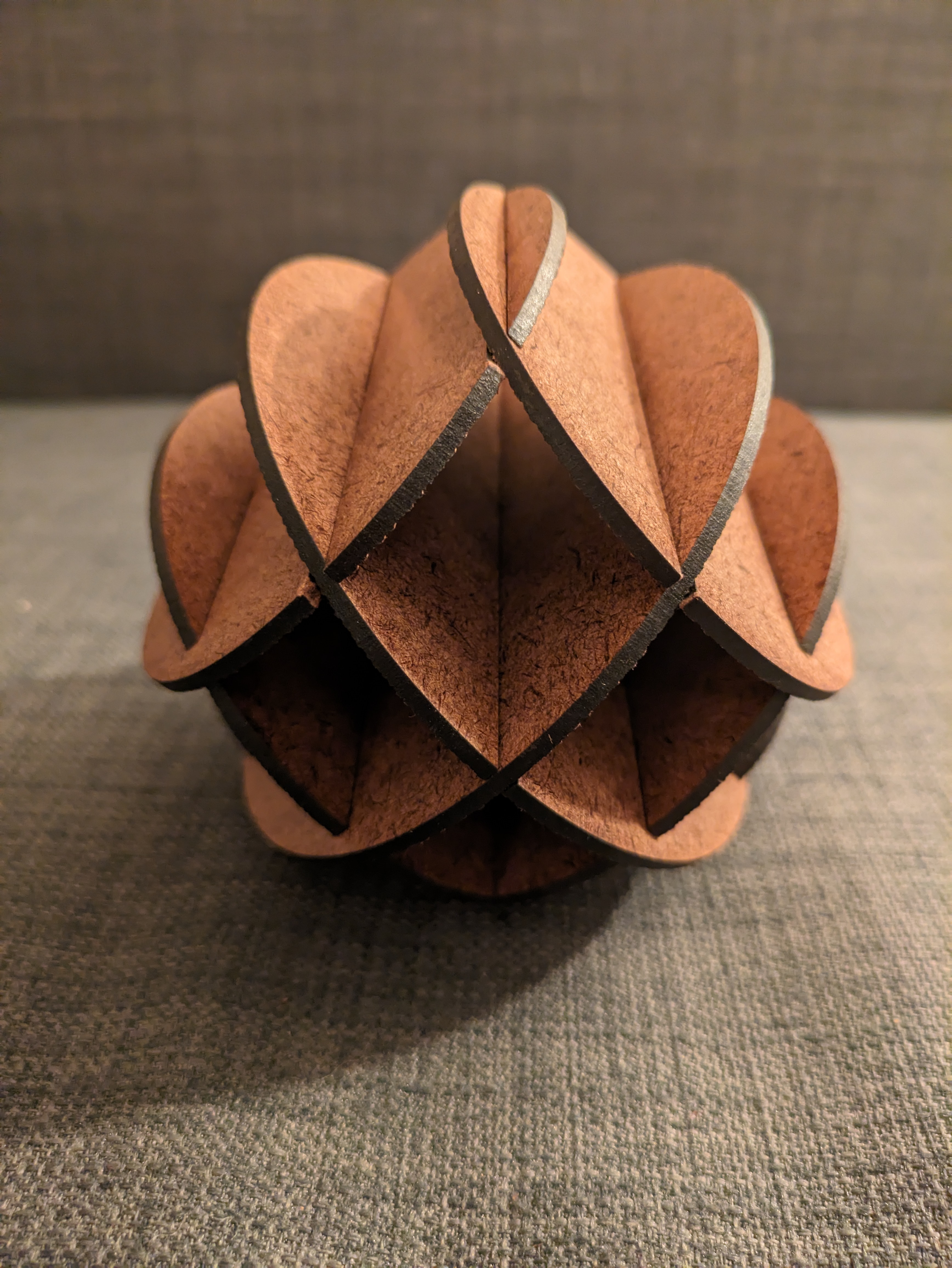
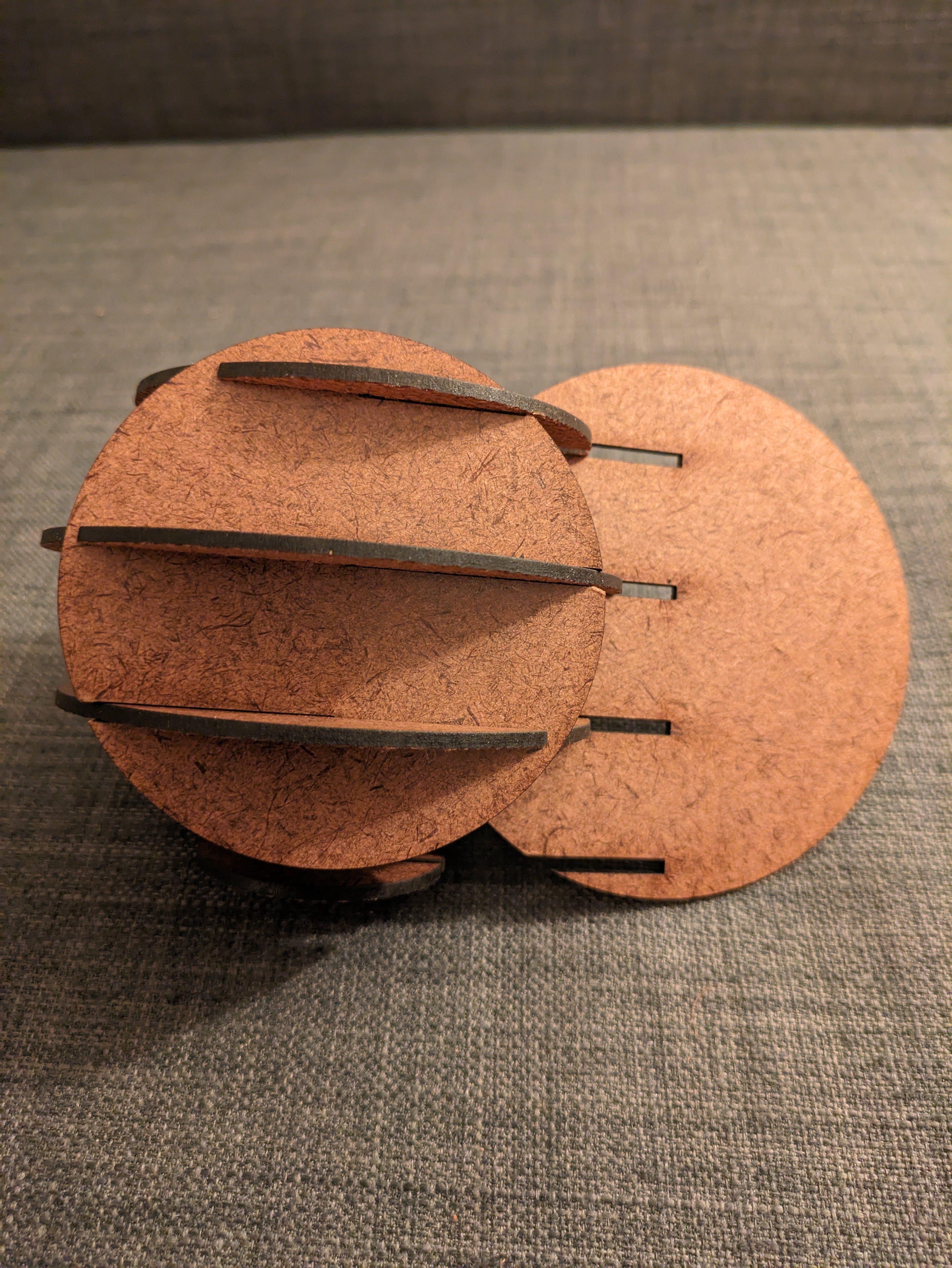
Note: I skiped part 1 of the extra credit and focused on part 2 (the slot joints). Although I will slice in both X and Z.
The diagram below provides a walkthough of how my algorithm works.

The user defined parameters for the slot joint slicer as shown below. Note that the material tickness no longer determines the layer height (layer spacing). End offset prevent the slicer from placing a joint on the leading edges. The three spacing parameters are for arranging and packing the slices for cutting.
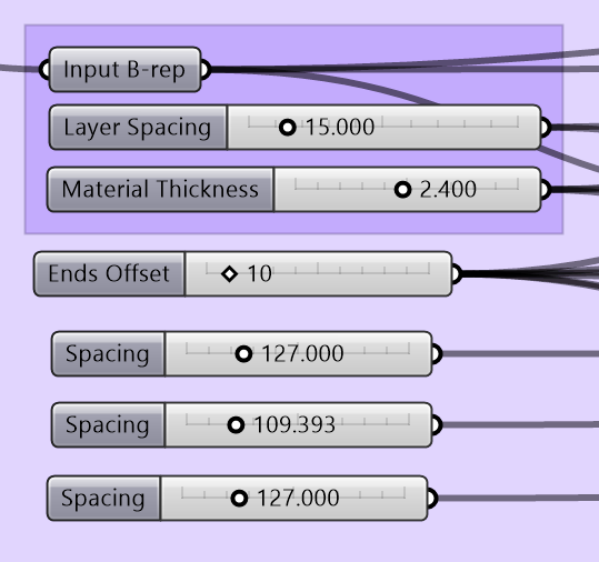
Note on kerf. It may take a few cuts to tweak the material thickness. If the slot joint is too tight, increase the material thickness. Likewise decrease if the joint is too loose.

Grasshopper Script
